I completed this circuit/project as a part of building my water sampling catamaran. The design actually went through four revisions, as various problems caused the first three controllers to fry in one way or another. The first three were somewhat unprotected circuit boards exposed to foreign material (dust, etc.) which was most likely their biggest problem, but the fourth revision has been in use on the water sampler for a while without any failure.
Design Goals
The goal of this project was to build a small, general purpose controller for 12V DC motors capable of handling current up to 20A. The controller would take a standard servo PWM waveform as an input, and output a voltage (really, just a high current PWM waveform) for variable, reversible control of motors. There are a plethora of commercially available speed controllers that fit this description, but I wanted a small form factor and the flexibility of programming in specific behaviors.
Issues from Early Revisions
All three first revisions eventually failed for one reason for another. While I did make schematic changes between each revision, the most important changes were in board layout. Obvious improvements include making power traces as wide as possible, and shorter; spacing power MOSFETs further apart; choosing MOSFETs that I could actually solder well with the tools at hand, and making the solder pads the best fit possible; providing a plastic bottom casing for protection; and adding a protective conformal coating. Less critical, but still important, developments in the schematic design included better led indicators (always more important than you think) and moving away from a complementary N-channel P-channel H-bridge design.
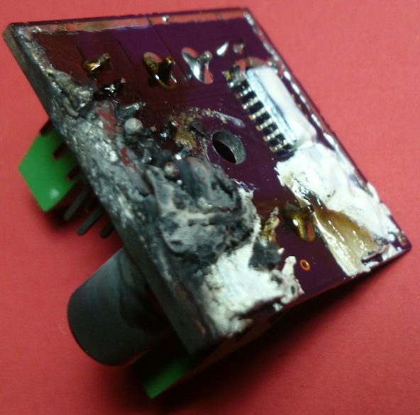
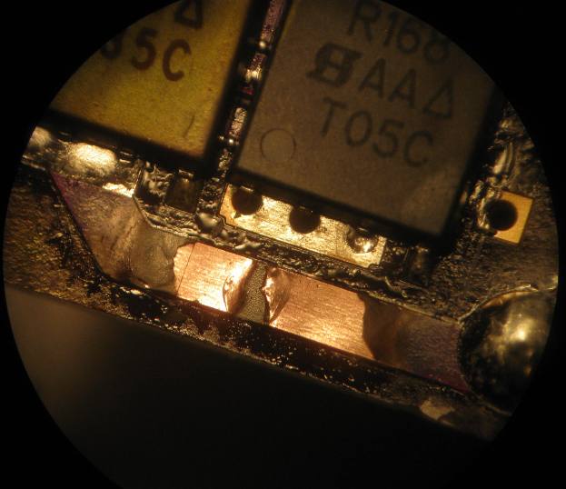
This speed controller took fire damage.
An undersized trace acted like a fuse when this controller's H-bridge shorted, which was probably due to bad soldering.
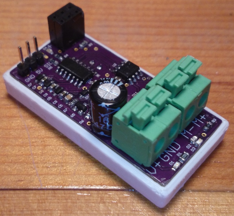
Final Design
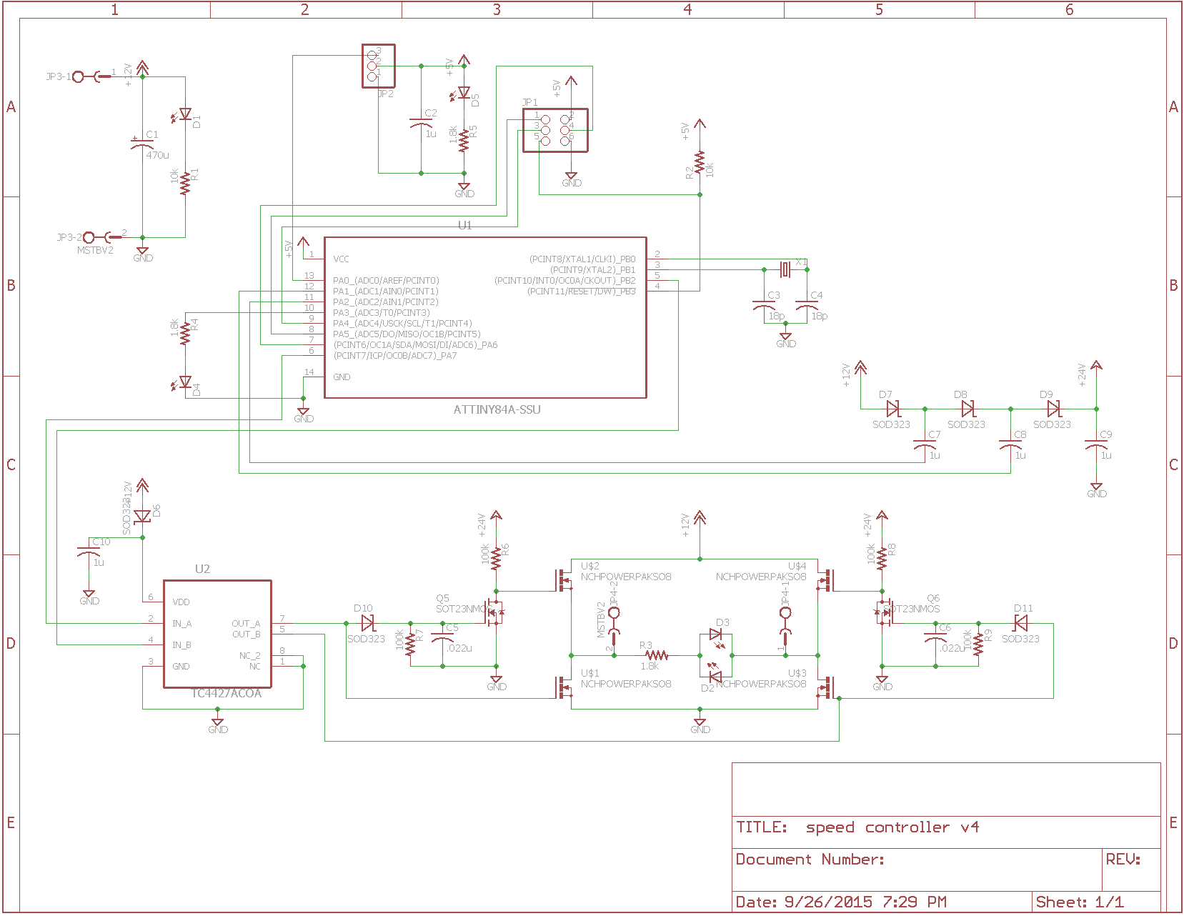
An ATTiny84 MCU controls the final speed controller. The MCU runs on 5V that it must receive along with the signal on the servo PWM header during normal operation. In addition to reading the input signal and controlling the speed controller's H-bridge, the MCU also operates a two-stage charge pump to control the high-side power MOSFETs. There is an AVR ISP header for programming the chip that can be used to modify the speed controller's function, and provide an extra input or output from the MCU for completing a servo control loop or anything else the hardware can handle. The H-bridge operates in a somewhat unique way. Each high side MOSFET is attached to a parallel RC circuit that keeps the high side switched off whenever there is any non-zero duty cycle to the complementary low side MOSFET. In this way, there are only two MOSFET drivers and no leakage current when the H-bridge is switching.
Design Files
Design files are here for anyone interested, including EAGLE shematic / board, firmware written in Atmel Studio, and an STL file for 3D printing the case.